Ceramic Capacitor Polarity Marking
Polarity Learn Sparkfun Com

Understanding Capacitor Codes And Markings Homemade Circuit Projects

Capacitor Conversion Values Reading Capacitor Values Capacitors Electronics Basics Electronic Engineering

Activity What Is Polarity And Why Do We Care Analog Devices Wiki
Capacitor Polarity For Various Types Based On Its Markings
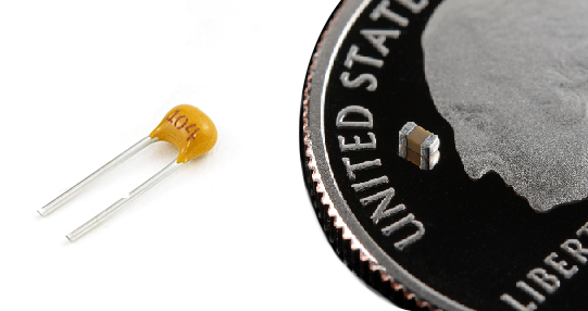
Is There Any Positive Negative Terminals In A Ceramic Capacitor 104 Quora

These capacitors are known for their polarized behavior.
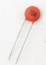
Ceramic capacitor polarity marking.
Ceramic Disc Capacitor Values Code Label
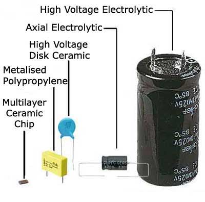
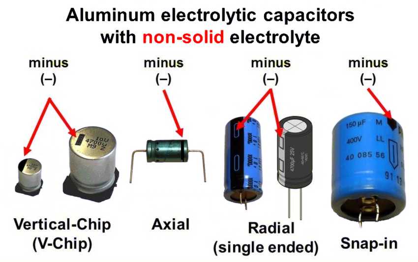
Electrolytic Capacitors Capacitor Symbols Macrofab

Led Ceramic And Electrolytic Capacitor Battery Scr Diode Schematic Symbol Electronics Basics Diode Electronics Projects

Electrolytic Capacitor Pinout Electrolytic Capacitor Electronic Schematics Capacitors

Tantalum Capacitors Advantages Considerations Arrow Com Electrolytic Capacitor Capacitors Electrical Projects
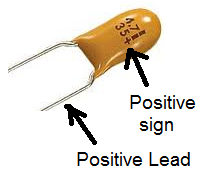
Tantalum Capacitor Polarity Markings

Basic Electronic Components Basic Science For Kids Electronic Components

How To Test A Capacitor Using Various Methods All About Engineering

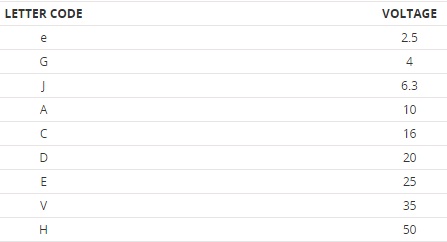
Coded Marking Pin Capacitor 1 In 2020 Electronics Circuit Electronic Schematics Electronic Circuit Projects
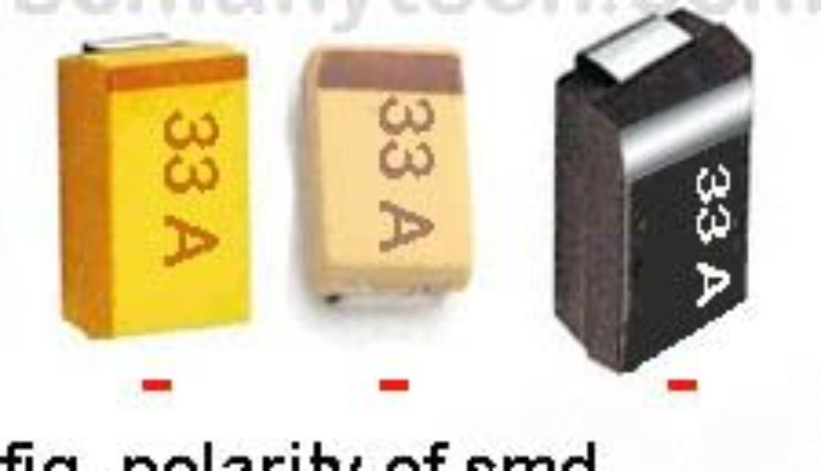
What Is An Smd Capacitor Common Capacitor Values Sm Tech
Capacitors

Capacitor Tips Re Antique Tube Radio Restorations
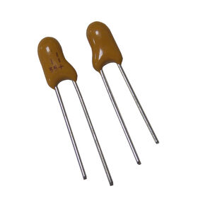
Tantalum Capacitor Polarity Marking Wholesale Tantalum Capacitor Polarity Marking Wholesalers Global Sources
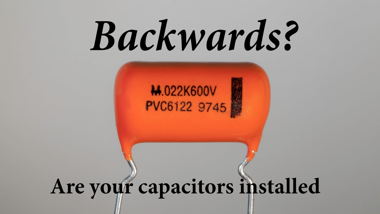
Are Your Capacitors Installed Backwards Build This And Find Out Youtube
Do Polymer Electrolytic Capacitors Have Polarity Murata Manufacturing Co Ltd
Capacitor Types Wikiwand

Homebuilt Rovs Electronic Organization Electronics Underwater Drone

How To Read Ceramic Capacitor Values Quora
1

Multilayer Ceramic Capacitor 50v 22uf Pack Of 20 Amazon Com Industrial Scientific

How To Detect The Reverse Polarity Of A Capacitor In A Pc Board Quora
Smd Capacitor Working Polarity Types Identification Based On Codes
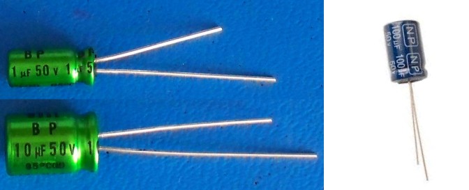
Non Polarized Capacitors
Common Questions Beginners Ask And Their Answers
Source : pinterest.com
